

E-mail: btomo@mail.ru; mail@btomo.ru.
Geometric Parameters of Cycloidal Gear

However, the gears sent for the repair very often differ by a larger number of teeth and have an output component connected to a big gear (internal one). For example, an auxiliary drive gear reducer of a ball mill.

Fig. 1 First stage of a disassembled cycloidal gear reducer
Overall gear ratio 886, double-stage first-stage module — 2.5 mm, second-stage module — 3.5 mm, number of first-stage gear teeth is 168 and 162, of the second-stage - 190 and 184, correspondingly, first-stage eccentricity 7.5 mm, second-stage — 10.5 mm, first-level tooth depth 5 mm, second-level— 7 mm. The correlation between a tooth and module depths differs from an involute one.

Fig. 2. First stage of an assembled cycloidal gear reducer. Cycloidal gear wheels view
To obtain a high qualification in the work with CGs, it is necessary to develop a theoretical base. For the specialists familiar with the configuration of planetary gears (PG) it would be convenient to start drawing analogies with the planetary ones and understand the CGs, and some authors even believe that a CG is a kind of a planetary gear [3, p. 217]. The planetary gears are geared linkage mechanisms where some components perform complex motions consisting of a transient (with a carrier) and relative (in relation to a carrier) rotating movements [4]. In this sense CGs are also covered by this definition. Common CG and PG components are epicyclic internal gears.

Fig. 3. First-stage epicycle of a cycloidal gear reducer which is a second stage input component
CG and PGB differences in external gears: the planetary ones have two external gears (sun and satellite). A sun is a central gear wheel rotating in relation to the main PG axis. A satellite (or a group of satellites) is an auxiliary gear wheel installed onto the bearings on the axis fixed at the carrier. CGs have one external gear (although they can have several similar gears as satellite groups in planetary gears). This gear has similar features with a satellite: 1) cycloidal CG wheel performs complex motion: a transient one with an eccentric part and a relative one towards such eccentric part; 2) it is engaged with a CG epicycle. The function of a PG sun gear wheel in a CG is performed by an eccentric part.
In the process of the CG study the following was identified: 1)![]() , where ∆z — difference in teeth number on CG crown and inside gear wheels, e — CG eccentricity (mm), m — module, mm;
, where ∆z — difference in teeth number on CG crown and inside gear wheels, e — CG eccentricity (mm), m — module, mm;
2) Reduction ratio: a) for a CG where an output shaft is connected with an epicycle, i = ![]() , where zБ — number of teeth on the epicycle (on a big gear wheel); b) for a CG where a carrier is an output i =
, where zБ — number of teeth on the epicycle (on a big gear wheel); b) for a CG where a carrier is an output i = ![]() , where zм — number of teeth on a small external inside gear.
, where zм — number of teeth on a small external inside gear.
A CG with an output from a carrier [1], a cycloidal gear wheel contacts with a carrier by rolling a gear wheel hole along a rundle. Initially, while analyzing an auxiliary drive gear reducer of a ball mill, it was supposed that the bearing upon the body frame is the same and is realized through the contact between the hole and rundle in the cycloidal gear wheel. However, this supposition was further rejected although it seems that such configuration is also possible.

Fig. 4. First stage of an assembled cycloidal gear reducer. Input shaft view
When considering the structure (see Fig. 1–4), it was identified that there are two cycloidal gear wheels working in a reversed phase. Each of them has a bearing assembly not only at the input eccentric shaft but also 4 bearing assemblies installed inside a body frame on the eccentric parts. As a result, it provides for the motion of each cycloidal gear wheel point in a circle with the radius equal to the eccentric one.

Fig. 5. CG reduction gear ratio
(in vertical direction) depending
on the difference in the ΔZ teeth number
on the epicycle and cycloidal gear (at Zэ=168)
The photo in Fig.4 shows:
1) all five eccentrics are installed in alignment (see the risks on the eccentric axes and the eccentric location in the center) and can work only synchronously. Therefore, one gear wheel cannot turn arbitrary in relation to the other one on its central bearing.
2) the part performing a rundle function in a CG "classical" configuration is just a part in this one connecting two box-type workpieces inside which two cycloidal gear wheels are installed;
3) bores in the gear wheels are made to provide for the spare location of these rundles while the diameter of the holes shall provide for the clearance between fixed rundles and the gear wheels performing complex motion.
4) A rotation torque is induced by a driving motor and passed to a central shaft through a shaft key while four peripheral bearing assemblies provide a body frame support.
The application of a gear reducer with the output epicycle instead of a gear reducer with a carrier output increases the reduction gear ratio of each stage only by 1 but as a result, the total reduction gear ratio increases from 840 to 886.
The CG reduction gear ratio depends on the number of epicycle teeth and the difference in the number of epicycle and cycloidal gear teeth as it is shown in Fig. 5. To select the set reduction gear ratio, it is necessary to choose Zэ. after assigning the possible difference ΔZ .
At the kinematic and power relations this CG is equivalent to the planetary mechanism with the twin satellites, epicycle and sun [4]. The force ratio has the following form: Мэ=Мс*к; Мв=Мс*(к-1); where к=Zэ/ΔZ; Мэ — epicycle torque; Мс — eccentric torque; Мв — carrier torque.
Cycloidal gear performance factor. The source [2] claims that the cycloidal gear reducer performance factor is 95% in one stage and 90% — in two stages. One shall make sure the CG performance factor is high. If one considers a CG as a PG kind, the performance factor is determined by a number of engagements. According to [4], a CG performance factor with one internal engagement is equal to 0.99. One shall specify if the losses were accounted for only in a gearing suggesting all other losses are considerably smaller. The issue needs to be further investigated. [3] provides a formula to calculate the gearing performance factor with the account of key losses:
η = 1 - (ψз + ψм + ψп)
where ψз — friction losses in the engagement, ψм — oil mix losses, ψп — friction losses in bearings.
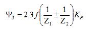
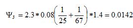
According to [3], let us take f=0.08, Kp=1.4, in the brackets the sign "plus" for external gearing, "minus" for internal gearing. Let us find out ψз for Z1=162 and Z2=168:
![]()
Let us ascertain that the same losses will be equal to 1% for a typical internal engagement with a significantly smaller number of teeth on the inside (small) gear wheel, as it is assumed in [4].
![]() , i .e. 0.6%.
, i .e. 0.6%.
While in case of external engagement they are close to 2%:
 , i .e. 1.4%
Thus, the less is the teeth number on a smaller gear wheel, the bigger are the losses.
It is reasonable to claim that the losses in the bearings and due to the oil mix are the same for shaft, planetary and cycloidal gears.
Therefore, a cycloidal gear has a performance factor advantage over all shaft and planetary gears due a high number of teeth on a small gear.
On the rotating torque induced by a researched cycloidal gear reducer. The gear reducer rotation is induced by an electrical drive with a nominal power of 7.5 kW at the rotation frequency of 900 rpm, therefore, a rotation torque at the gear reducer input is 80 Nm. At the output ω=1 rpm while Мкр= 80*900=72,000 Nm.
For the sake of comparison, a required rotation torque at the final gear reducer output of the tractor TM-10 produced by DST Ural, LLC, can be assessed by a propulsive effort of driving wheels with 10 tons at each side and the driving wheel radius:
Мвк = 100000H * 0,43m = 43000 Nm
Therefore, the CG can be also applied as a final gear reducer of an industrial tractor.
Conclusions:
- The cycloidal gear circuit with an epicycle output was studied;
- Such circuit is equivalent to a planetary gear with the twin satellites, epicycle and sun in terms of force and kinematic relations.
- The authors established the dependences between the number of gear teeth, cycloidal gear ratio and eccentricity;
- The article demonstrated the CG advantage over the shaft and planetary ones in terms of the performance factor;
- The authors developed recommendations for the CG design with the pre-set gear ratio;
- The opportunity to apply a CG as a final gear reducer of an industrial tractor, class 15-20, was considered.
References::
- Wikipedia. Cycloidal Gears. https://ru.wikipedia.org/wiki
- Internet source. http://www.darali.com/page17.html
- Reshetov D. N. Machine Parts: Manual for Students of Mechanical Engineering and Mechanical HEI Specialities. — 4th edition., revised and completed — M: Mechanical Engineering, 1989. - 496 p.
- Filichkin N. V. Analysis of Planetary Gears of Transport and Traction Machines: Manual — Chelyabinsk: Ed. of SUSU, 2005. — 175 p.