

E-mail: btomo@mail.ru; mail@btomo.ru.
Synthesis of Bevel Gears with Multipair Engagement

Fig. 1. Worn-out bevel gear wheel with cleavages at the teeth tops.
Effective provision for their bearing capacity and resource is a complex scientific and technical task. Traditional solutions, by increasing the resistance of gears to existing loads and the accuracy of their manufacture, are expensive and not always effective. An alternative way is to reduce contact pressures on the teeth while simultaneously interacting several pairs of teeth, i.e., on the basis of a multipair engagement.
A similar effect is achieved by increasing the length of the active tooth engaging line by modifying the engagement geometry, in particular, by the profile depth modification of the basic rack profile. In the n-paired gear, where n=2,3…, is the relation of the active contact line length AD relation to the gear pitch AB, where A and D are the points of contact line intersections with addendum circles (Fig. 2), must always be greater than n, where n is the quotient of the profile length factor ε α .
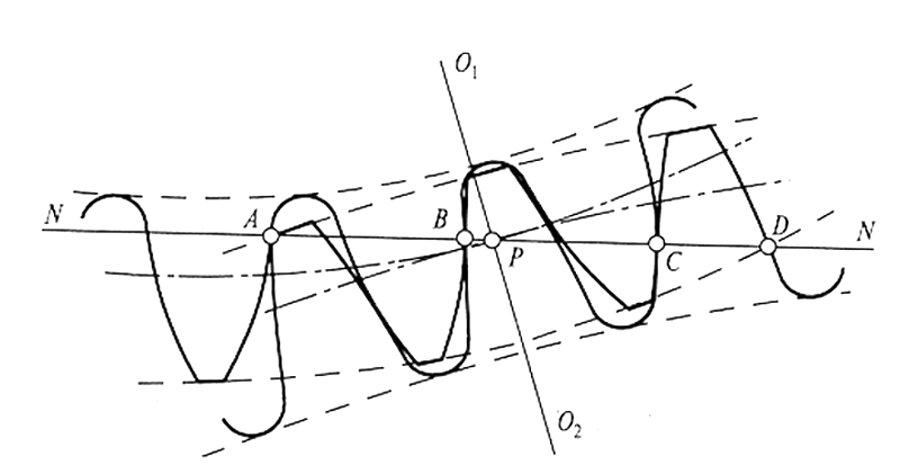
Fig. 2 Multipair (2-pair) engagement diagram
The implementation of a multipair gear contact is possible by increasing the active engagement line, when the contact ratio is numerically greater than two, i.e., the following condition must be fulfilled:
εα > 2. (1)
The condition (1) is met by modifying the initial data based on the computer simulation of the gear geometry. As the analysis of the expressions determining the geometry of bevel gears [1], [2] shows, the value of the factor εα depends mainly on the values of the parameters of the basic rack profile, number of teeth, factors of the offset and tooth inclination angle, i. e.
εα = F(zc, xc, α, ha*, β) > 2, (2)
where zc, xc are the total values of teeth numbers and profile shift factors of gear pairs; α, ha*, β are the profile angle and the rack tooth profile head height factor and the tooth inclination angle.
The multipair gear geometry is determined by the profile depth modification of the basic rack profile within the limits of:α ≤ 20°; ha* >1, and also of possible misalignments of the profile. In the n-paired gear, where n is the quotient of the offset factor εα, the value of engagement pairing n is determined as the function of εα value, i. e.
n = INT (εα), (3)
where INT is the operator of the function of the largest integer not exceeding a given numerical value.
In general, the active engagement line consists of two sections — zones of n-paired and (n+1)-paired engagement. In this case, the quotient of the factor εα, i.e., INT (εα) = n, and the fractional part defines the area (n+1)-of paired engagement. The gearing calculation using condition (1) is performed taking into account the analysis of the potential values of the contact ratio εα0[3]:
![]() , (4)
, (4)
εα0 factor values for separate basic rack profiles are shown in the Table 1.
Table 1. Hypothetical values of the factor εα0.
|
αº |
ha* | εα0 | αº | ha* | εα0 |
|
14,5 |
1,0 |
2,626 |
20,0 |
1,0 |
1,980 |
|
14,5 |
1,5 |
3,939 |
20,0 |
1,5 |
2,971 |
|
14,5 |
2,5 |
6,566 |
20,0 |
2,5 |
4,952 |
|
17,5 |
1,0 |
2,220 |
22,5 |
1,0 |
1,801 |
|
17,5 |
1,5 |
3,330 |
22,5 |
1,5 |
2,701 |
|
17,5 |
2,5 |
5,549 |
22,5 |
2,5 |
4,502 |
As seen from the Table 1, for gears with standard profile parameters, the condition (1) is theoretically not feasible. The implementation of this condition is only possible by modifying the basic rack profile. In general, for manufacturing the paired gears a gear cutting tool is used, corresponding to the selected rack tooth profile. In certain cases when manufacturing the gears with depth modifications of teeth, if α=20°,and ha*>1, standard tools can be used, as the tool profile height factor ha*≤2,4 2,5. In particular, by reducing the radial clearance in the transmission to 0.05÷0,1 of the module m within the permissible limits, it is possible to increase the teeth profile depth and to ensure the condition (1). Table 2, for example, shows the factors εα values for double-pair bevel spur gears with a profile depth modification and initial data excluding interference of the teeth. The gearing calculation is carried out with values of m=1, since the factor value in the general case does not depend on the modulus.
Table 2. εα factor values for 2-pair bevel gears with profile depth modification
|
z1 |
x1 | z2 | x2 | αº | ha* | c* | εα |
|
25 |
-0,2 |
51 |
-0,55 |
20 |
1,18 |
0,02 |
2,085 |
|
27 |
-0,2 |
54 |
-0,55 |
20 |
1,2 |
0,05 |
2,112 |
|
29 |
-0,2 |
58 |
-0,55 |
20 |
1,2 |
0,05 |
2,126 |
|
31 |
-0,25 |
63 |
-0,6 |
20 |
1,2 |
0,05 |
2,147 |
|
33 |
-0,27 |
99 |
-0,63 |
20 |
1,2 |
0,05 |
2,199 |
where z1, z2, x1, x2, c* are the teeth numbers and factors of the profile shift and radial clearance.
As follows from Table 2, the total depth of teeth can be increased, for example up to 2.45m with the modification of the basic rack profile depth while using a standard tool , which leads to the formation of a double-pair contact. For bevel gears with a curved tooth shape, in particular a circular one, the implementation of a double-pair engagement with a standard tool is only possible with small tooth inclination angles up to 7. Further increase in engagement pairing is possible mainly by decreasing the profile angle α and increasing the depth factor, i.e., due to the profile depth or only tooth depth modification, when ha*> 1.25 m. In these cases, a special tool is used to manufacture the gears.
In general, the synthesis of n-paired bevel gears is possible for any arbitrary values. Tables 3 and 4, for instance, show the factors εα values for three-pair transmissions with straight and circular teeth with m = 1 without undercutting and interference of teeth with profile parameters according to the RF patents for utility models [4], [ 5]. Similar data on 4-pair gears [6], [7] is presented in Tables 5 and 6.
Table 3. εα factor values for 3-pair bevel gears with straight teeth
| z1 | x1 | z2 | x2 | αº | ha* | c* | εα |
|
31 |
0,25 |
65 |
-0,3 |
17 |
1,7 |
0,2 |
3,101 |
|
37 |
0,15 |
71 |
-0,4 |
16,5 |
1,75 |
0,2 |
3,331 |
|
40 |
0,1 |
81 |
-0,45 |
16 |
1,8 |
0,2 |
3,539 |
|
41 |
0,3 |
83 |
-0,3 |
15 |
1,85 |
0,2 |
3,710 |
|
47 |
0,3 |
95 |
-0,3 |
14,5 |
1,9 |
0,2 |
3,953 |
Table 4. εα factor values for 3-pair bevel gears with circular teeth
|
z1 |
x1 | z2 | x2 | αº | ha* | c* | εα |
|
37 |
0 |
75 |
0 |
16,5 |
1,775 |
0,25 |
3,102 |
|
39 |
0 |
81 |
0 |
16 |
1,8 |
0,25 |
3,224 |
|
41 |
0 |
83 |
0 |
15 |
1,85 |
0,25 |
3,305 |
|
43 |
0 |
87 |
0 |
14,75 |
1,875 |
0,25 |
3,329 |
|
45 |
0 |
91 |
0 |
14,5 |
1,9 |
0,25 |
3,493 |
Table 5. εα factor values for 4-pair bevel gears with straight teeth
|
z1 |
x1 | z2 | x2 | αº | ha* | c* | εα |
|
57 |
0,1 |
115 |
0 |
14 |
1,9 |
0,2 |
4,221 |
|
59 |
0,1 |
119 |
0 |
14 |
1,9 |
0,2 |
4,241 |
|
61 |
0,1 |
123 |
0 |
13,5 |
1,95 |
0,2 |
4,458 |
|
63 |
0,1 |
127 |
0 |
13,5 |
1,95 |
0,2 |
4,478 |
|
65 |
0,15 |
131 |
0 |
13 |
2,0 |
0,2 |
4,690 |
Table 6. Factor values for 4-pair bevel gears with circular teeth
|
z1 |
x1 | z2 | x2 | αº | ha* | c* | εα |
|
63 |
0 |
127 |
0 |
14,5 |
1,9 |
0,25 |
4,117 |
|
65 |
0 |
131 |
0 |
14,5 |
1,95 |
0,25 |
4,227 |
|
67 |
0 |
135 |
0 |
14,0 |
2,0 |
0,25 |
4,438 |
|
69 |
0 |
139 |
0 |
13,5 |
2,05 |
0,25 |
4,661 |
|
71 |
0 |
143 |
0 |
13,5 |
2,1 |
0,25 |
4,775 |
In the Table 4 factors εα were determined with angle value β= 25, and in table 6 with β = 10º.
When analyzing the gearing strength, the bevel gear is considered an equivalent cylindrical gear with a module equal to the average module of the bevel gear. The design stresses at the bevel gear pitch point in a multi-pair gear according to the standard [8] will be determined using the expressions:
![]() ; (5)
; (5)
![]() , (6)
, (6)
where σH, σF are the design contact and bending stresses, respectively
on teeth, MPa;
KH, KF are the load factors, respectively, for contact and bend;
Ft is the total circumferential force on the pitch cylinder in the transverse section, N;
KZ is the factor taking into account the mechanical properties of gear material, surface matching patterns, total length of contact lines and tooth inclination angle;
KY is the factor taking into account the influence of tooth shape and strain concentration;
Kn is the factor of uneven load distribution between teeth in the multipair engagement, equal to 1.1, 1.25 depending on the contact size, stiffness, accuracy, etc.;
bw, dw are the initial diameter and width of the gear, mm;
u is the gear ratio.
The dependences (5) and (6) allow for direct determination of the strength endurance of the gears, taking into account the engagement pairing.
As seen in the tables (3) - (6) the values of factors εα for gears with straight and circular teeth differ very slightly considering approximately equal values of the numbers of gear teeth and the corresponding parameters of the basic rack profile. Herewith, the load on the teeth with multipair engagement decreases depending on the contact pairing increase, In the first approximation, the strength endurance of the multipair gears in comparison with consistent single-pair gears increases on the average by n times in bending and in √n times on the contact. This allows, with neighbor values of the factors ε α , to replace the gears with a circular tooth with spur gears, which are significantly less labor intensive in manufacturing.
As a result, due to the implementation of the multi-pair engagement, it is possible to significantly increase the bearing capacity and strength of the bevel gears, and in many cases it is preferable to use the spur gears as more technologically advanced ones. For example, cutting the straight gear teeth by circular pulling, as the most productive method. Such a replacement is particularly effective in the repair and modernization of equipment, when cutting bevel pairs with circular teeth is a problem, and the spur gear can be cut with the use of any horizontal milling machine using disk gear cutters and a dividing device.
Conclusions
1. Synthesis of bevel gears with arbitrary n-pair engagement for the purpose of improving their quality is possible mainly only when the basic rack profile is modified. Multipair gears with a standard profile are theoretically not feasible.
2. The implementation of the multipair engagement is only possible for 2-pair gears.
3. The most effective application of double-pair spur gears is during equipment repairs or upgrades.
4. The possibilities for synthesizing multipair bevel gears with any value of n are limited only by the practical importance of using such gears.
V. Z. Melnikov, Cand. Tech. Sci., assistant professor MSIU
References
1. GOST 19624 — 74. Bevel Spur Gears. Geometry Calculation. M.: Publisher of Standards, 1974. 26 p.
2. GOST 19326 — 73. Bevel Gears with Circular Teeth. Geometry Calculation. M.: Publisher of Standards, 1974. 75 p.
3. Melnikov V. Z. Synthesis of Gears with Random N-paired Engagement. Mechanical Engineering Bulletin. 2010. No. 4, p. 29–31.
4. Taratynov O.V., Melnikov V.Z., Bolotina Ye. M. Bevel spur gear with three-paired engagement. Patent of the Russian Federation for a Utility Model No.131110. Bull. No. 22 of 10.08.2013.
5. Melnikov V. Z. Bevel Gear with Circular Teeth with Three-Paired Engagement. Patent of the Russian Federation for a Utility Model No, 134265. Bull. No. 31 of 10.11.2013.
6. Melnikov V.Z., Taratynov O. V. Bevel Spur Gear with Four-Paired Engagement. Patent of the Russian Federation for a Utility Model No. 142182. Bull. No. 17 of 20.06.2014.
7. Melnikov V. Z. Bevel Gear with Circular Teeth and Four-Paired Engagement. Patent of the Russian Federation for a Utility Model No, 139974. Bull. No. 12 of 27.04.2014.
8. GOST 21354 — 87. Cylindrical Involute External Gear Wheels. Strength Calculation. М.: Publisher of Standards, 1988. 128 p.